


This is the TinyTrak developed by Byon Garrabrant.

The unit's heart is a PIC16F84 prgrammable PIC, it contains the firmware to run the unit. The TinyTrak takes raw NMEA sentences from a GPS receiver and transmits the position at the user specified intervals.

The TinyTrak is configured through and COM port of a PC and by a small Windows prgram. The program allows for editing of Call, Digipath and Transmit intervals.

Here is the schematic for the TinyTrak.
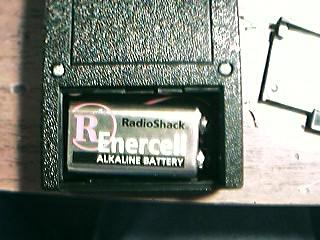
I built my unit with a RadioShack project box, some clear diffused LEDs, Cat 5 stranded wire, a 9 volt battery connector, some small gauge shielded cable and a small SPST toggle switch. The whole unit fit neatly into the project box along with the 9 volt battery. (Shown Below)
I orginally installed a 3/32" mono jack for audio connection. I used a small piece of shielded cable for the connection from the jack to the board. This setup proved to be worthless since it was affected very easily by RFI. I then chose to solder the shielded cable straight to the board and installed a 3/32" connector on the other end so I could easily connect the TT to any of my HTs.
 |
 |
|---|---|
 |
|
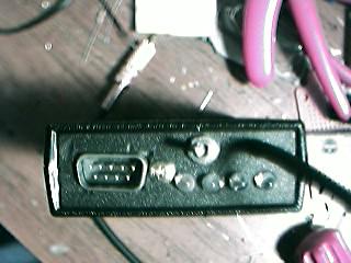
I chose to install a DB-9 male connector into my unit so I could connect my Garmin GPS cable directly to it without having to make a custom GPS cable. I made sure to switch the Send and Receive data pins to allow for a "null modem" configuration. A null modem adapter is needed to connect directly to the PC for configuration.
 |
 |
|---|
I mounted the clear LEDs to the front panel and used wire-wrapping wire (blue) to connect them to the board. I used regular plastic model glue to hold the LEDs in the panel. I also mounted the DB-9 male and power toggle switch to the front panel. (Shown Below)
 |
 |
|---|---|
 |
|
The TinyTrak II has been out for a while and I had one to build I just did'nt get it done till now. There were some major changes made to the firmware and one change to hardware. The PIC16F84 was replaced with a PIC16F628 chip. The 16F628 has the same pin configuration of the 16F84 but has more code space and can run faster. The firmware had SmartBeaconing added for speed compensated beaconing, as well as CornerPegging.
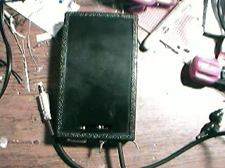
I finally finished my TinyTrak II. I put this one in a new, smaller case. I also made this TT more "connectable". By that, I mean, I put a DB-9 female on one end for the power and radio connections. On the other end I put in a DB-9 male for the computer/GPS connection. I put in a male so it will accept my already made Garmin cable. I also swapped the TX/RX pins so I don't need a null-modem adapter for the GPS. I only need the adapter for programming from the computer. Below is a picture of the finished unit.

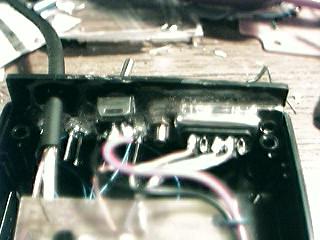
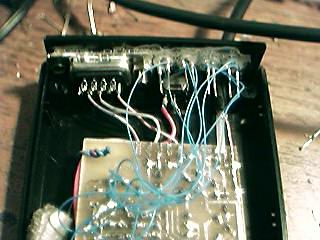
Below is a shot of the insides of the TT2. You'll notice I opted to NOT put in a power switch on this one. I also tried to keep the wire short and twisted all of the grounds around the other matching wires to help keep the RFI down. I may need to come back and add in some small ferrite beads if RFI becomes a problem. The power was the only thing I wasn;t really worried about with RFI, but that may become a problem too, we'll see.

Below is a diagram of how I wired out the radio/power interface. I did'nt stick with traditional Kantronics style. The bottom row of pins are unused at the moment and I plan to eventually wire a couple to the Configuration pads on the TT PCB.

Here is a picture of a tracker I put together using my Yaesu VX-1R, Garmin GPS III Plus and TinyTrak II. You can see the interface cable connected to the left side of the TinyTrak II. The cable includes connections for Radio and Power. This is part of my "MicroTracker" and "MicroAPRS" setups.