- A Special Thanks to:
- Jim Mellon KA3IDN - Lots of 900 MHz guidance/tips and source of radios
- Dave Kinsey KS4BO - Cut and welded the rack
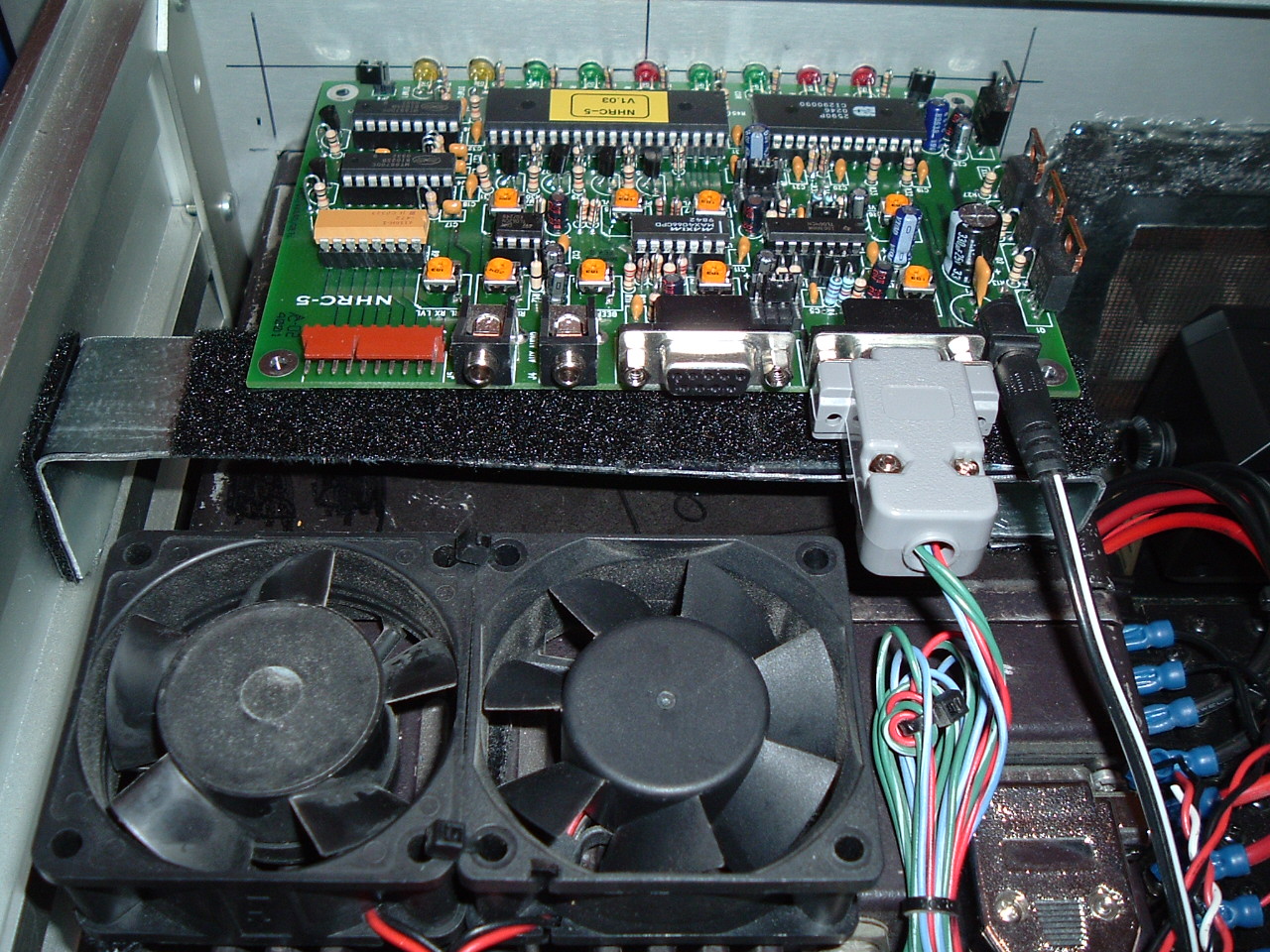
- Gerry Clark K4GWC - Controller
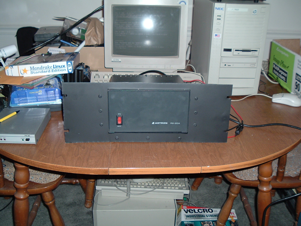
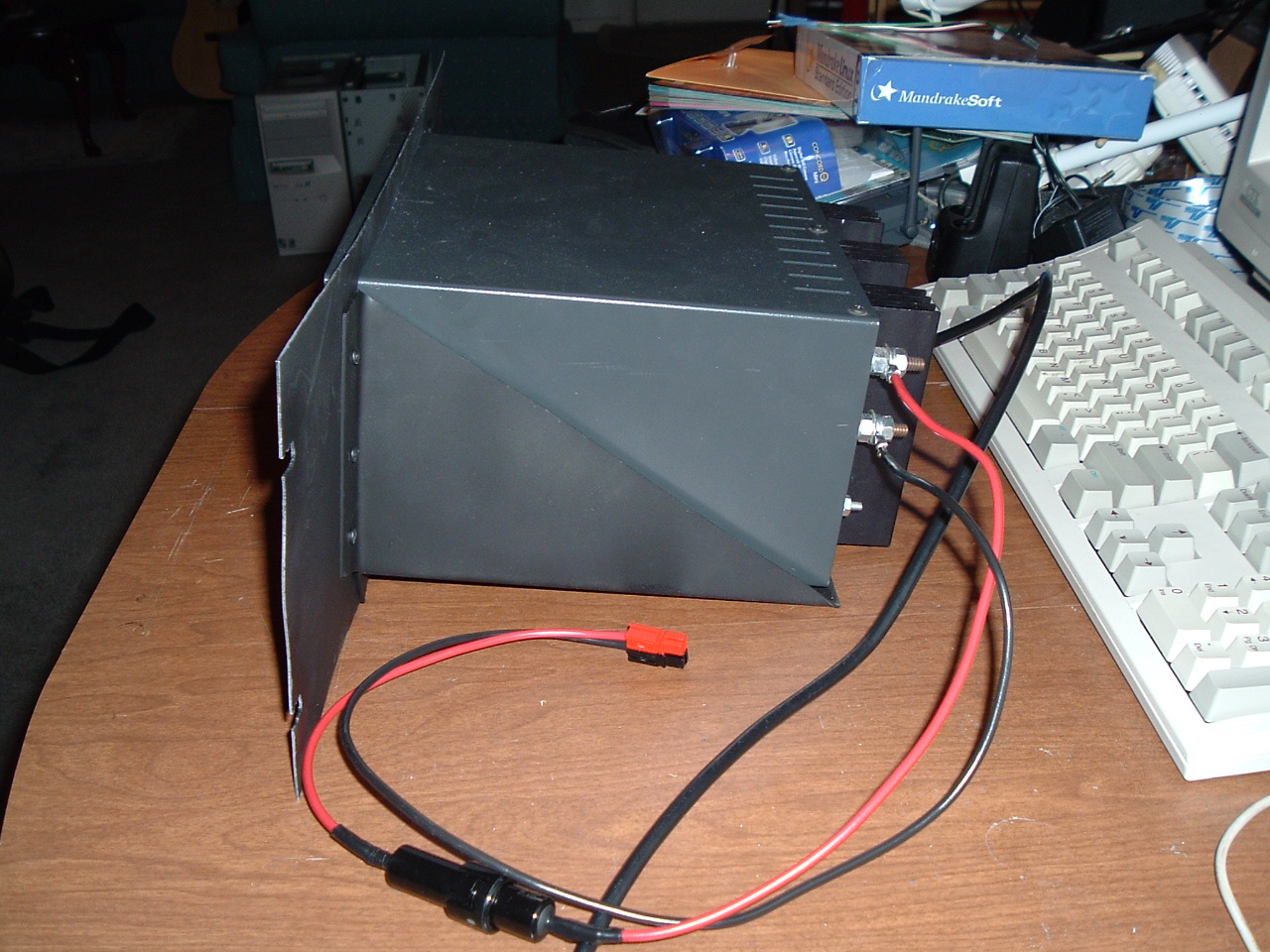
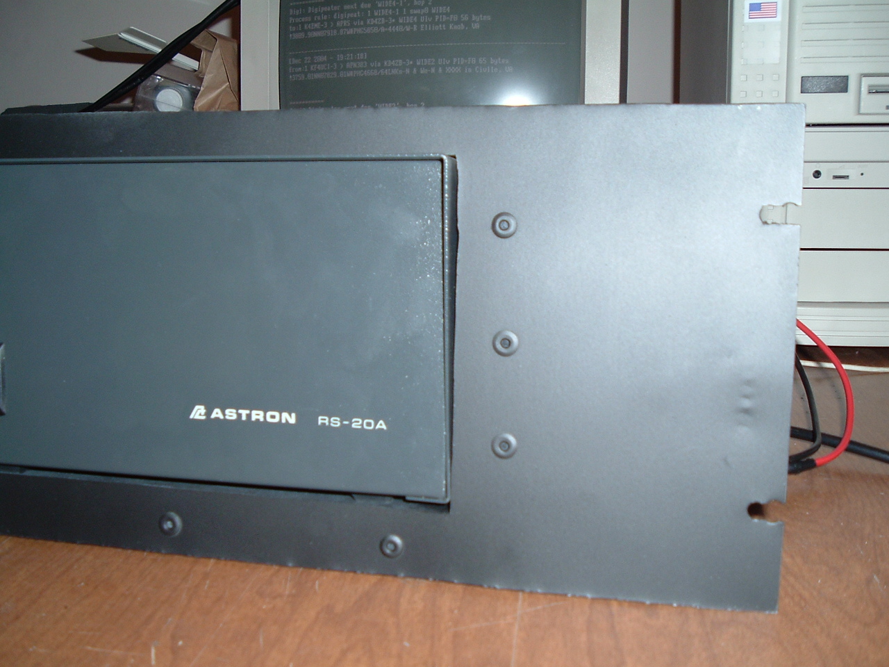
- Fred Krack K4HVB - Power Supply
- Doug Rorrer and Pat Lewis N3AYW - 1/2" Hardline
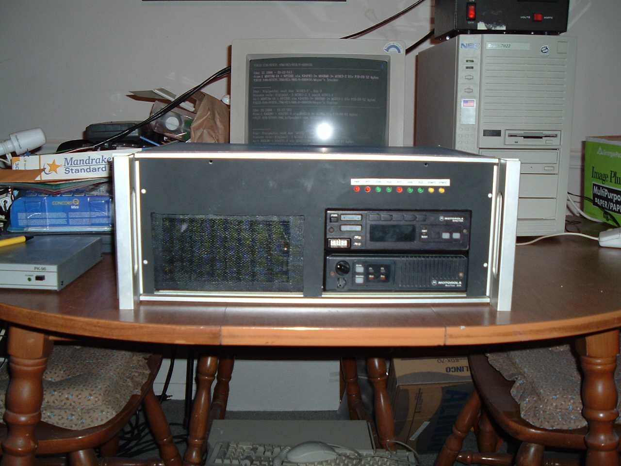
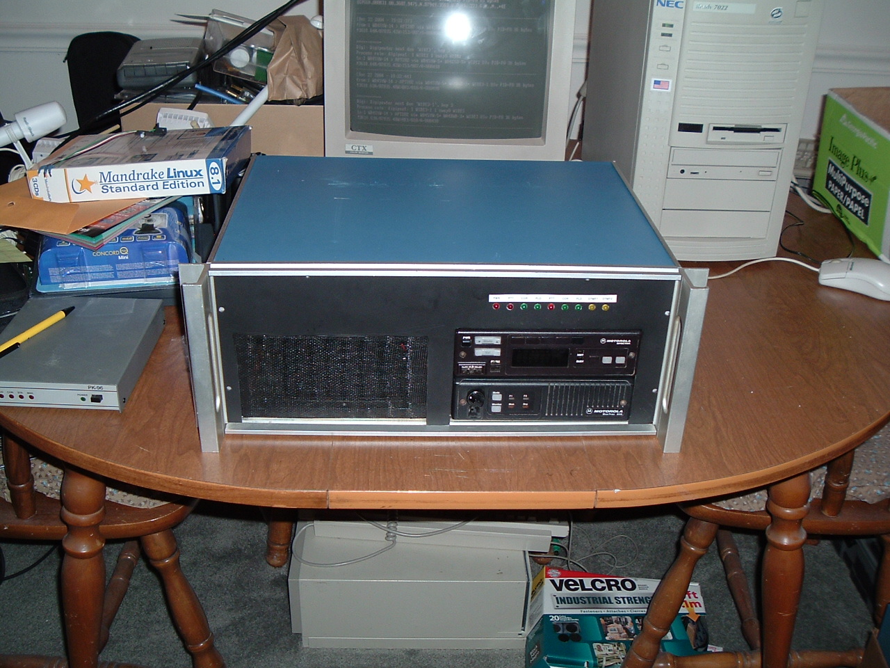
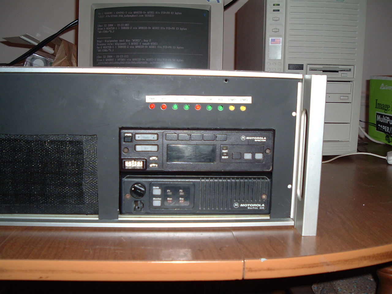
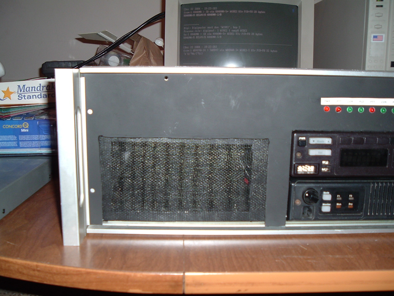
Four Crackheads Repeater Group |
|||
| Home | ((( Our Repeaters ))) | Status | About Us |
|---|---|---|---|
| Frequency Pair: | |||||
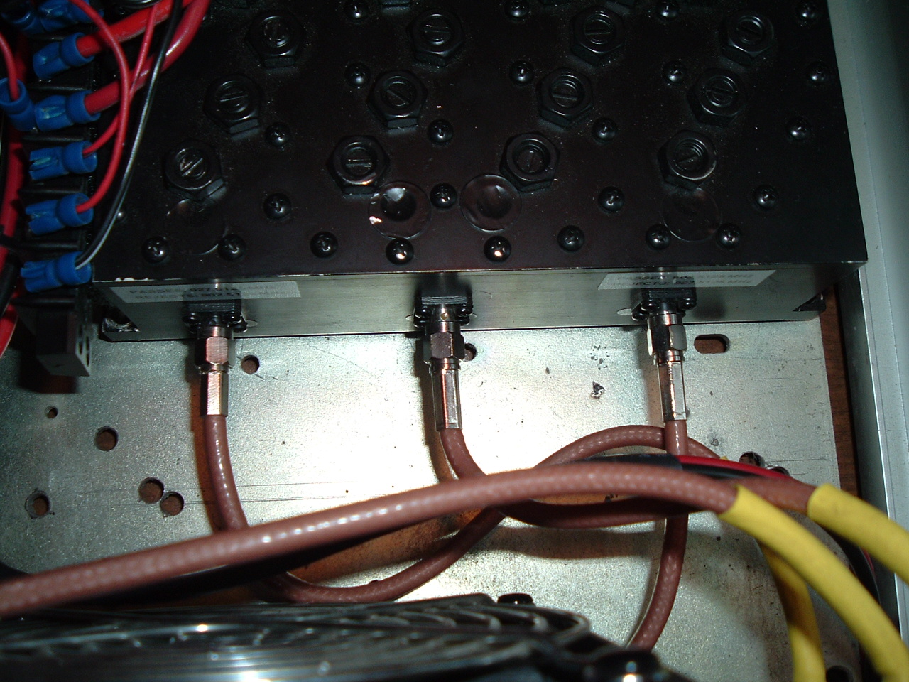
| Transmit: | 927.5125 MHz | Receive: | 902.5125 MHz | PL | 100.0 Hz |
|---|---|---|---|---|---|